
bosch map sensor pinout Wiring Flow Line
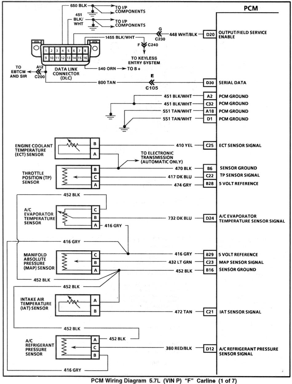
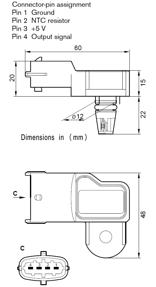
GM 3 Bar Map Sensor Wiring Pinout. It's pretty straightforward to use this with any of our aftermarket EMS options. As per the wiring diagram above, you can: Wire Pin A to Sensor Return/Ground at the ECU. Wire Pin C to 5-volt vref from the ECU. Wire Pin B, the Sensor Output, to the ECU's MAP Sensor Input.

350z maf sensor wiring diagram
MAP Sensor & Wiring DiagramAmazon Printed Bookshttps://www.createspace.com/3623928Amazon Kindle Editionhttp://www.amazon.com/Automotive-Electronic-Diagnostic.
Dodge Map Sensor Wiring
Follow the steps below: Locate the 3 pin MAP sensor on your engine. Connect one wire to the MAP sensor's power terminal and attach it to a 5V power source. Connect another wire to the MAP sensor's ground terminal and attach it to a nearby ground source, such as the engine block. Connect the remaining wire to the MAP sensor's signal.

data fb [25+] Honda Map Sensor Wiring Diagram, Gm 3 Bar Map Sensor Wiring Diagram
Knowing the wiring schematic of the MAF sensor is important for testing the sensor or other related work. This includes 3, 4, and 5-wire-MAF sensor configurations. 3-Wire MAF Sensor. Consists of three wires: Hot Power Wire (reference voltage from ECU), Ground Wire, and Signal Wire (transmits signals to ECU). 4-Wire MAF Sensor.

Pin on Automotive electrical
You are watching: 3 & 4 Pin MAP Sensor Wiring Diagram: Effectively Wire it Up. Map sensing units are commonly found on the side of the intake manifold near the throttle body. The sensor functions by the adjustments induced by the intake air pressure used on the silicon chip. This sensor plays a crucial duty in the efficiency of an engine.
Mass Air Flow Sensor Wiring Diagram Diagram Stream
Understanding the basics of 3-wire sensor diagrams is essential for anyone working with industrial automation and control systems. These diagrams show the wiring connections and configuration of sensors that use three wires for communication and power supply. The three wires include a power wire, a ground wire, and a signal wire.
MAP sensor Wiring diagram Pressure sensor, others, electrical Wires Cable, adapter, schematic
A three-wire sensor has 3 wires present: two power wires and one load wire. The power wires will connect to a power supply and the remaining wire to some type of load. The load is a device that is being controlled by the sensor. The most common type of load would be a PLC (programmable logic controller) DC input.
Gm Map Sensor Wiring Diagram Herbalmed
Wiring Diagrams for 4-Wire Oxygen Sensors: 4-wire oxygen sensors, also known as air-fuel ratio sensors, offer better precision compared to their 1, 2, and 3-wire counterparts. They consist of two wires for the heater circuit and two wires for the sensing element. The sensing element wires connect to the PCM, with one wire serving as the signal.

Conexión de sensor MAP Business International Medina SAC
52-1708 8" G-Series Shock Sensor. 52-1711 11.5" G-Series Shock Sensor RIFE MAP Sensor Calibration. 1 Bar MAP Sensor. 2 Bar MAP Sensor. 3 Bar MAP Sensor. 4 Bar MAP Sensor. 5 Bar MAP Sensor. 7 Bar MAP Sensor. 10 Bar MAP Sensor RIFE Pressure Sensor Calibration. 60 psi transducer. 100 psi transducer. 150 psi transducer. 200 psi transducer. 300 psi.
Ifm Level Sensor Wiring Diagram Wiring Diagram Pictures
Identify the grounding point: Look for a screw or terminal labeled "GRD" or "GND" on the motion sensor light fixture housing. This is where the ground wire will be connected. Connect the ground wire: Insert the exposed end of the ground wire into the grounding point and tighten the screw or secure the wire with a nut.
map sensor wiring PLZ HELP! VW Vortex Volkswagen Forum
The sensor provides valuable data to the engine control unit (ECU) for fuel management and engine performance optimization. Understanding the wiring diagram for a 3 wire map sensor is crucial for proper installation and troubleshooting. The 3 wire map sensor typically consists of three pins: signal, ground, and power.
Wiring Diagram Database Ls1 Coolant Temp Sensor Wiring Diagram
MAP sensor 2 • From TPS sensor, the full close signal is inputted, but from the MAP sensor, the signal voltage exceeds 2.0 V: Exhaust manifold temp. sensor • Receiving an out of range "- 46 to + 170 °C (- 50.8 - +338 °F) (0.10 - 4.6 V)" signal. Fuel injector • No operation signal from the ECM. Throttle position sensor
3 Way Motion Sensor Switch Wiring Diagram Wiring Diagram
Step 1: Gather the necessary tools and materials. Before you begin wiring, make sure you have all the tools and materials you need. This may include a wire stripper, electrical tape, a multimeter, and the appropriate wires for the sensor. Step 2: Identify the sensor's wires.
Home » Shop » Sensors » Pressure Sensors » Bosch 1 Bar TMap Map Sensor with IAT
The diagram below shows the typical wiring for these sensors.. The external MAP sensor in the above diagram is optional and may be omitted if the onboard MAP is used. Alternatively an external Baro sensor may be added in the same was as an external MAP; A 3 wire variable TPS is required. On/Off type throttle switches are not suitable
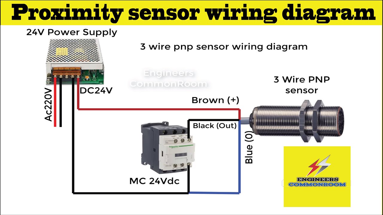
3 Wire Proximity Sensor Wiring Diagram
A 3 wire PT100 wiring diagram is a diagram that illustrates how to properly connect a PT100 temperature sensor with three wires. PT100 is a type of resistance temperature detector (RTD) that is widely used in industrial applications to measure temperature accurately. It is designed to have a resistance of 100 ohms at 0 degrees Celsius.

cruzeiro Faça tudo com meu poder Incapacidade vw map sensor pinout quadrado Giotto Dibondon Caius
MS3-Pro Wiring Quick Reference Guide. MS3-Pro Wiring Quick Reference Guide. February 20, 2015. White connector pinout. Pin unctionF Wire color Stripe / shielding 1 High current out 1 Light green None 2 High current out 2 Light green Dark blue 3 Injector out J White elloYw 4 Injector out I White Gray 5 High current out 3 Light green Red 6 CKP+.
- Haier 8000 Btu Air Conditioner
- Walking On A Cloud Fairview Mall
- Centre Intégré De Mécanique Industrielle De La Chaudière
- Ccm World Invite Chicago 2023
- Chartwell Seigneuries Du Carrefour Résidence Pour Retraités
- Houses For Sale West Saanich Bc
- Jeep Electrique Enfànt 2 Places
- Saskatoon Sport And Leisure Show
- Almonte District Community Centre
- Faire Son Nid 5 Lettres